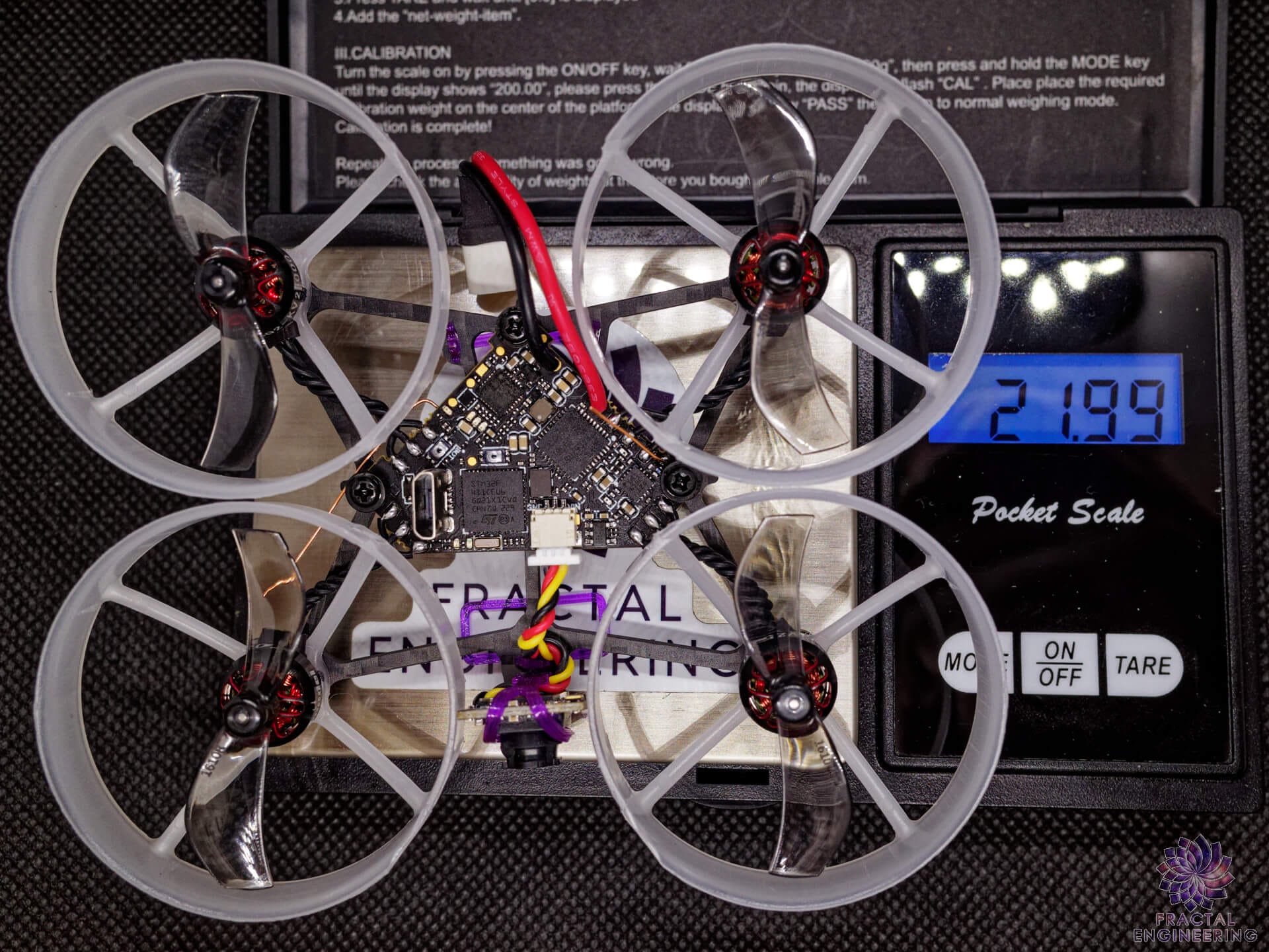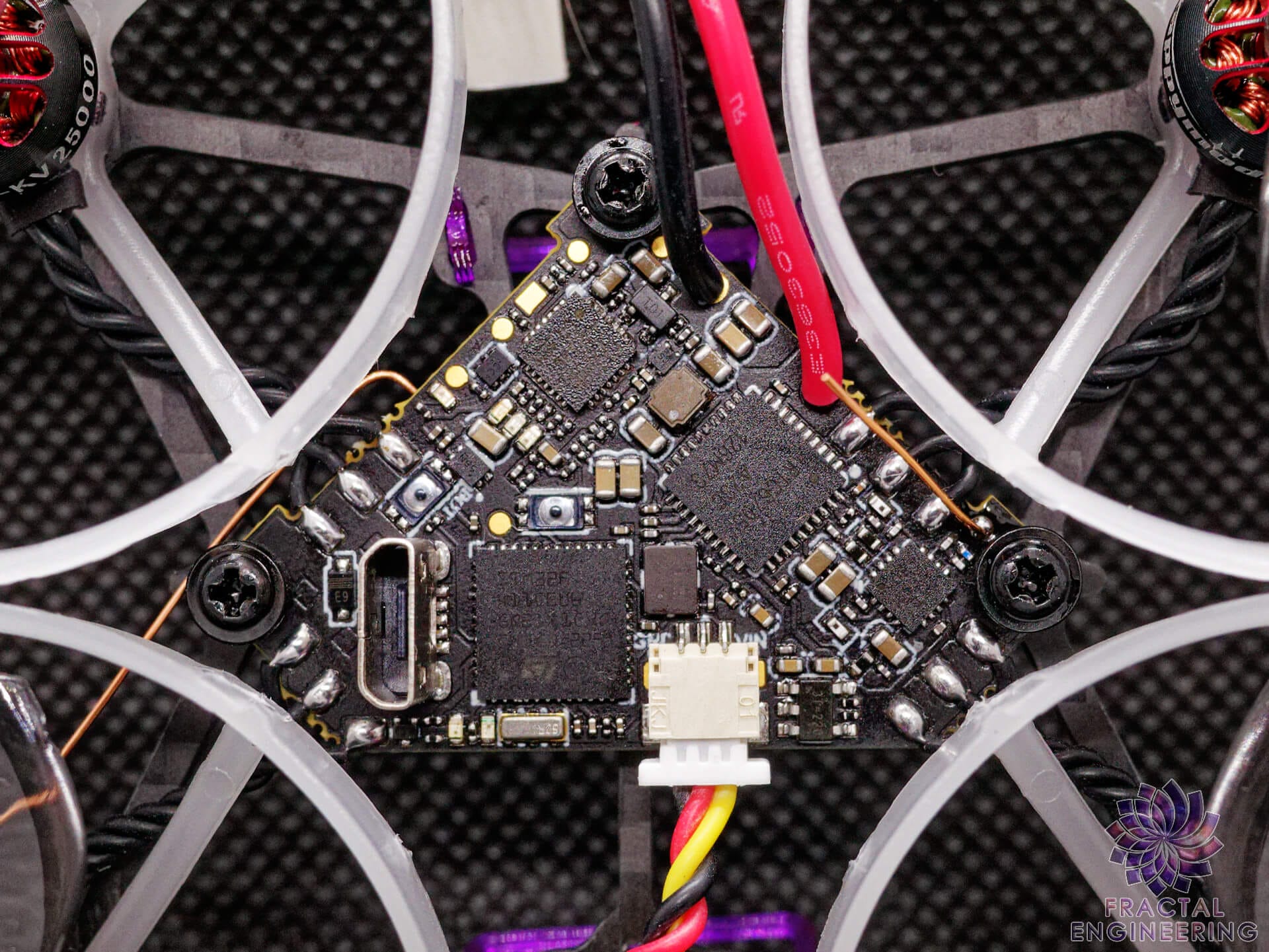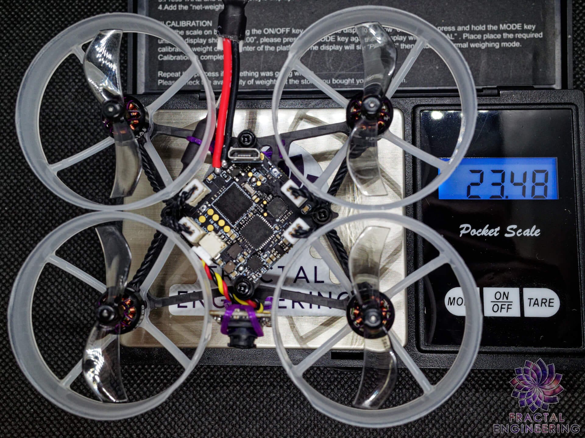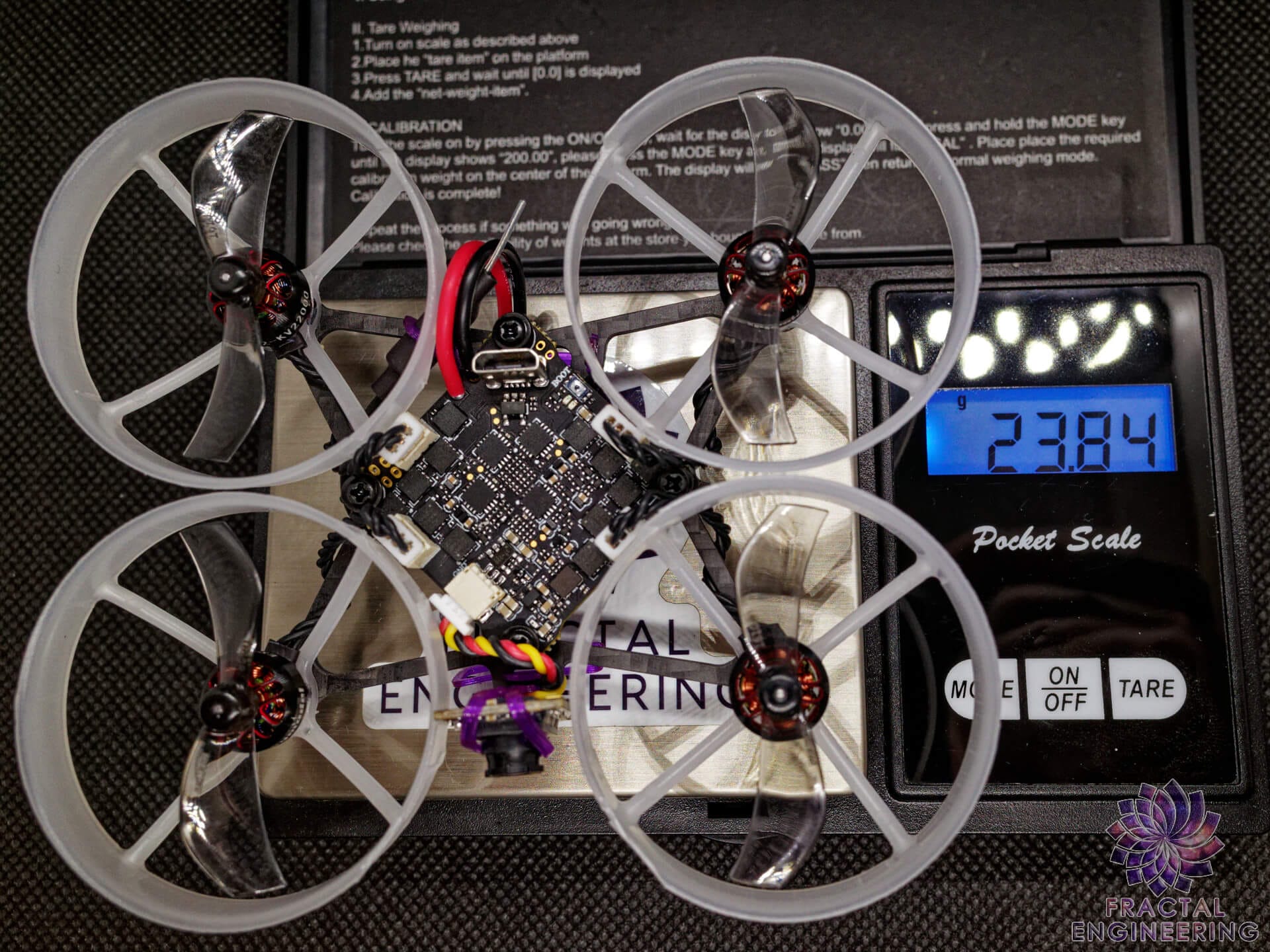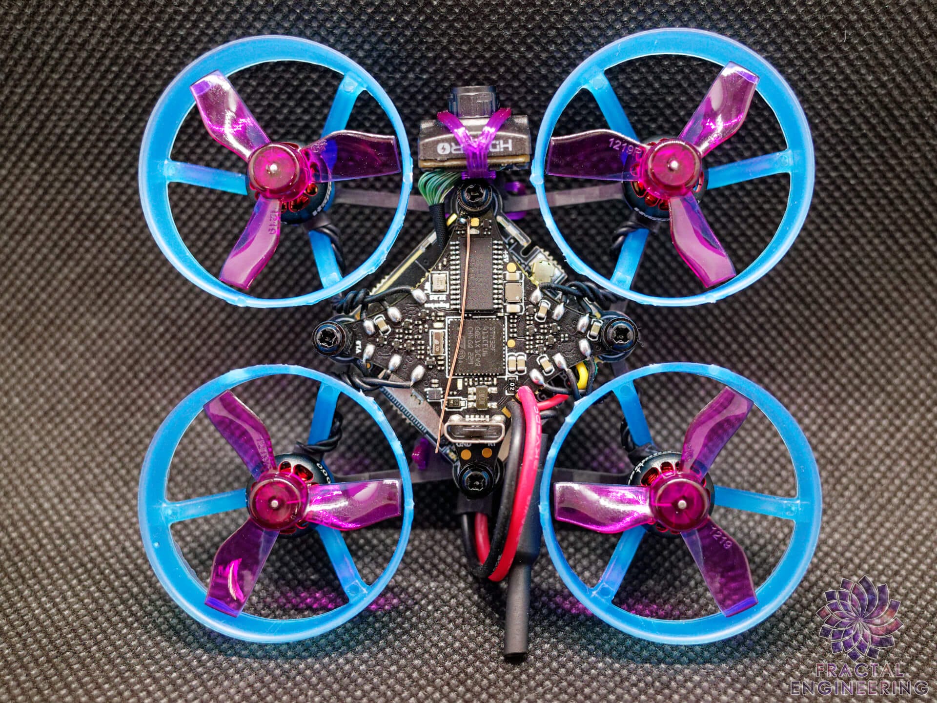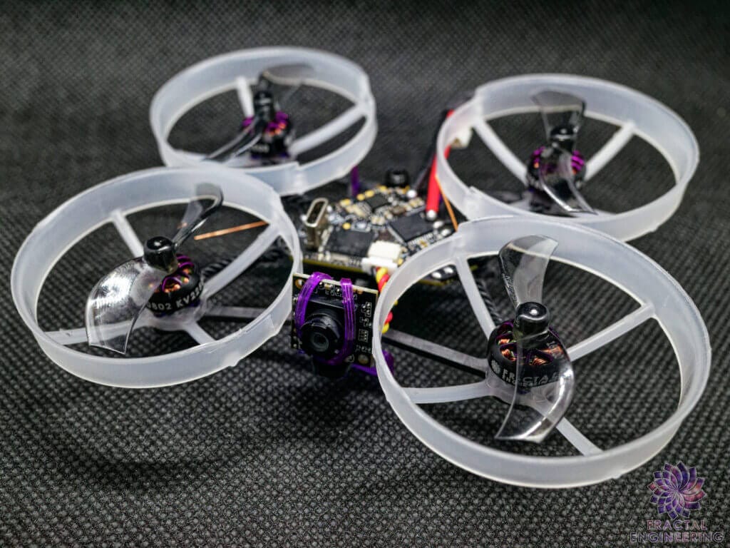

Thank you for purchasing your Fractal Whoop!
Your support is truly appreciated and we’re humbled that you chose to trust my vision with this high-performance racing whoop frame.
This page will be the instruction manual on building, tuning or just getting familiar with your setup so that you may get the most out of it.
First of all, if you’re not the reading type, you may rewatch one of the many assembly livestreams I’ve made over time for every possible configuration.
Or follow me there for updates on the ongoing developing builds
This will be the extended documentation detailing how I build my BNF.
Table of Contents
Got a BNF?
An even bigger thanks for entrusting us to buid your whoop so you may experience it just like I’ve designed it!
And well as a result, a lot of what’s described below will already have been done for you.
And if you chose to have yours prebound with your ELRS bind phrase you may not even need any of it!
You may nonetheless find some useful infos on upgrading it later on in the firmware section, or simply rebuild it.
Cheers and happy flying!
Electronics Assembly
For most build I recommend starting with the electronics so you may test every subsystem before it’s all tucked in the frame.
As a general rule, I like to proceed as follows:
- Open all electronics; FC/AIO FC, VTX, Camera, receiver. Inspect for factory defects, solder blobs, lifted components
- Open motors, check for free spinning bells by hand, inspect threads for debris and magnets to be well seated. Tuck in any wire sticking out.
- Flash FC, check for every system that can operate on USB; usually gyro, RX bind, eventually VTX on AIO, OSD and Camera feed.
- Then plug in/solder motors, apply battery power (preferably through a current limiting power supply) and flash/test ESCs by spinning motors
Analog Builds
I do not force you to use the diamond 👀
HM Diamond F4
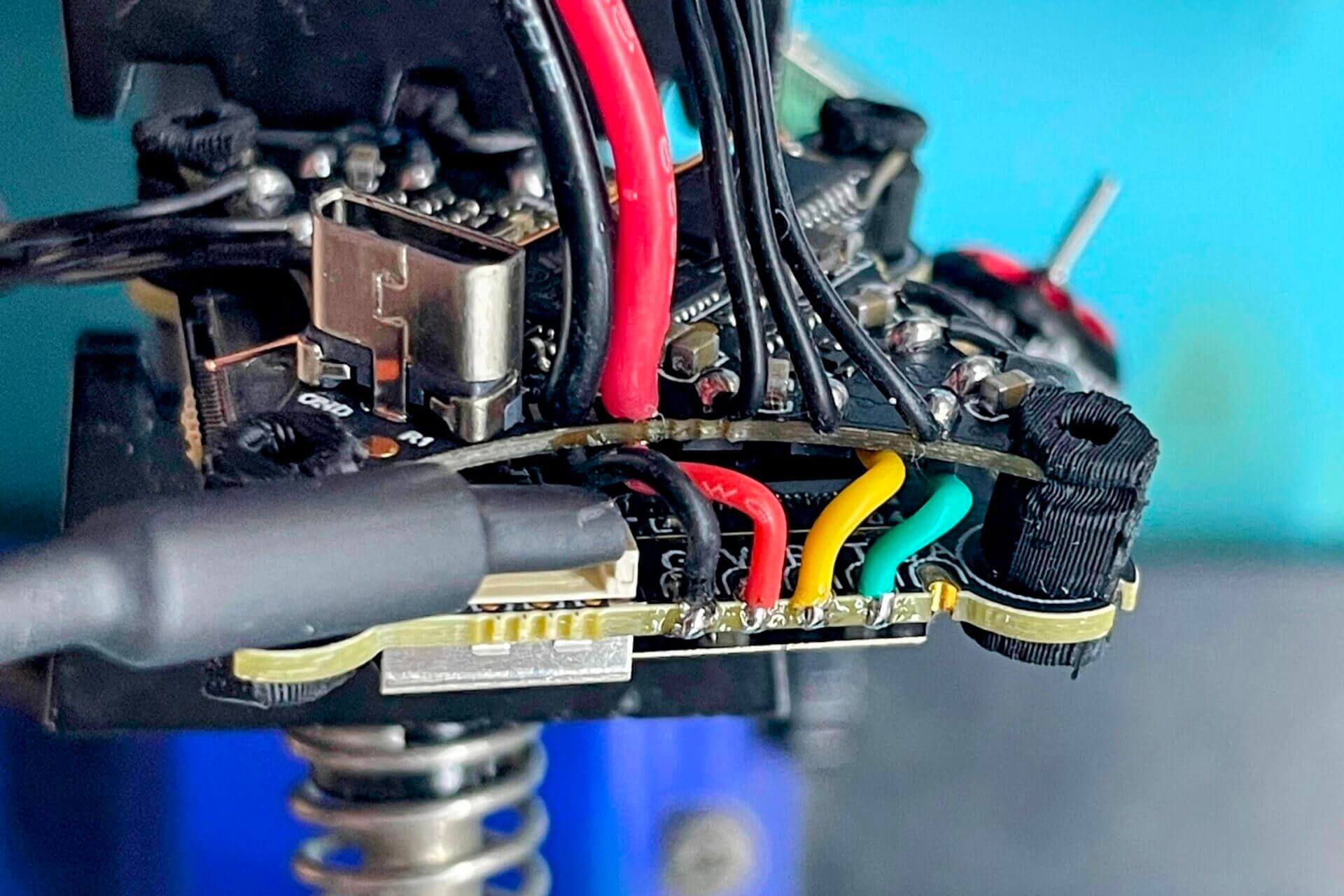
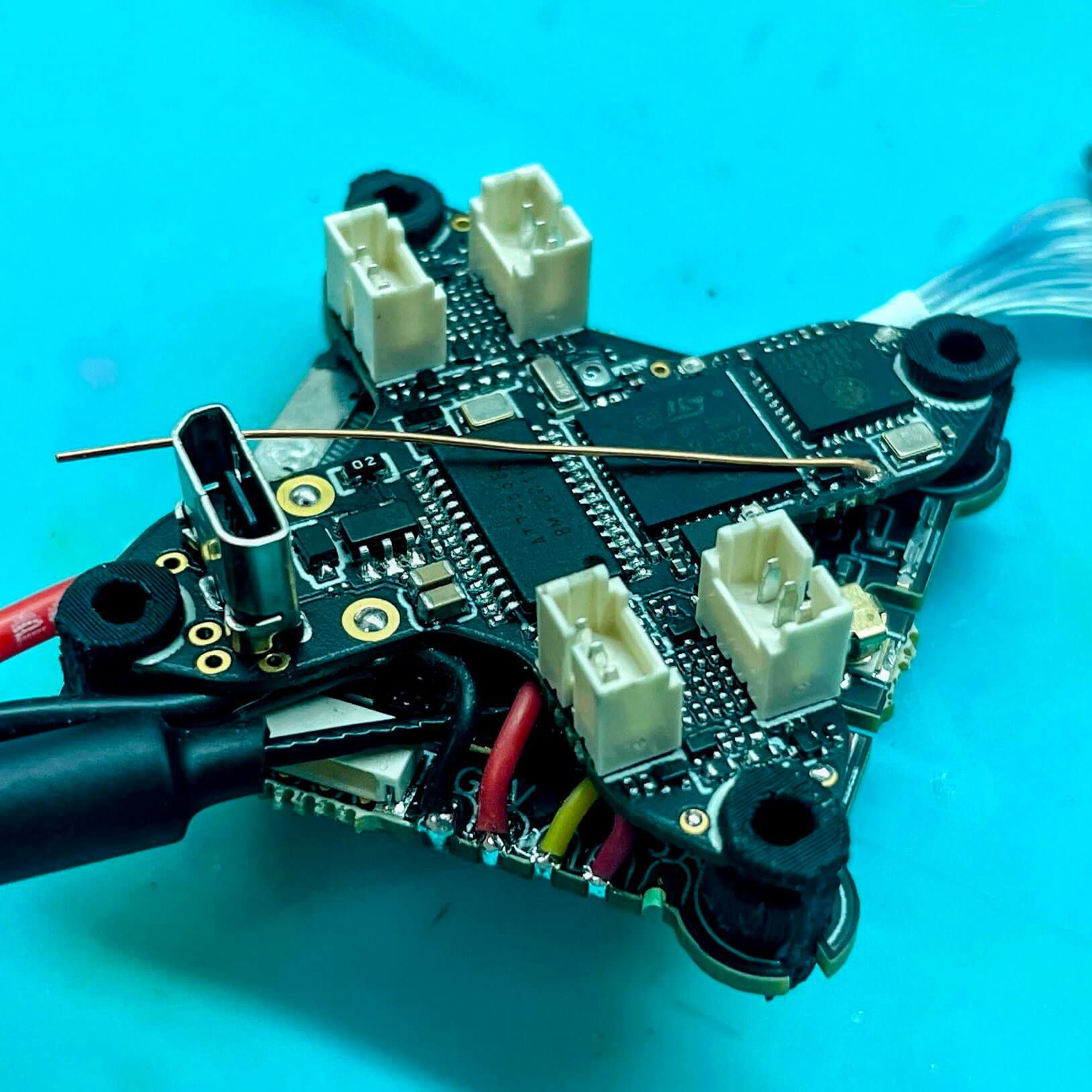
Solder the pigtail on the top, through hole or flush to the board, extending backwards (cut gnd wire shorter)
Cut the motor wires. Distance from the edge of the bell:
- 23mm for F65, twisted 3-4x
- 25mm for F75, twisted 3-4x
Desolder Rx antenna, solder it back facing outwards, perpendicular to the FC edge. Trim to 31.2mm and fold forward right after the edge.
Desolder VTX antenna. solder it back on the top. Trim to 12.9mm. bend back along the FC edge, 45deg (should get up to right below the top of the duct.
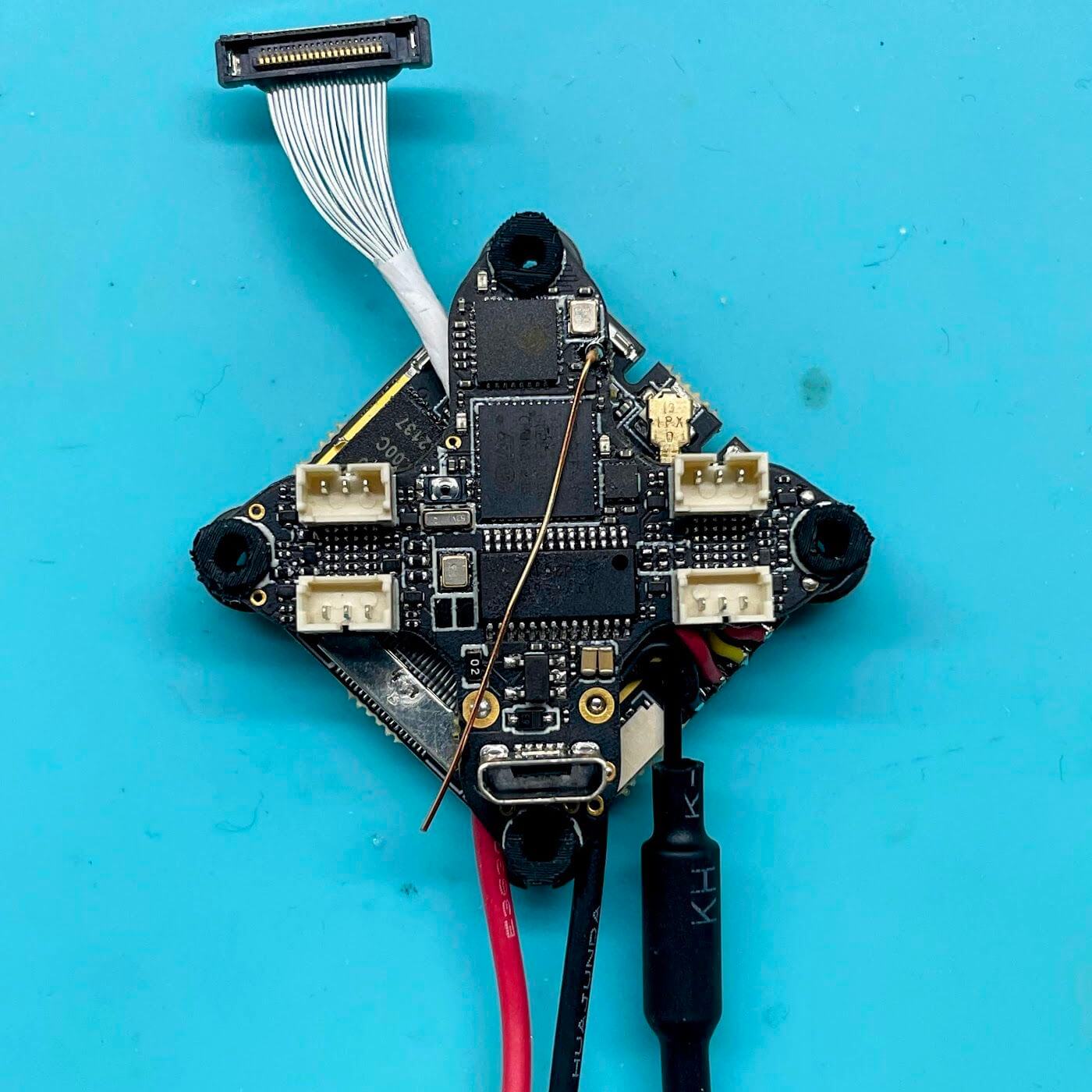
Assemble the FC to the bottom plate, USB facing UP
Use short M1.7x5mm screws, short grommets
HM ELRS F4 2G4
Solder the pigtail on the top, through hole or flush to the board, extending backwards (cut gnd wire shorter)
Assemble the FC to the bottom plate, USB facing UP
Use long M1.7x6mm screws, cut the included grommets top and/or bottom to clear the CF but fit the screw
Twist the motor wires 4-5x and lay down along the CF braces
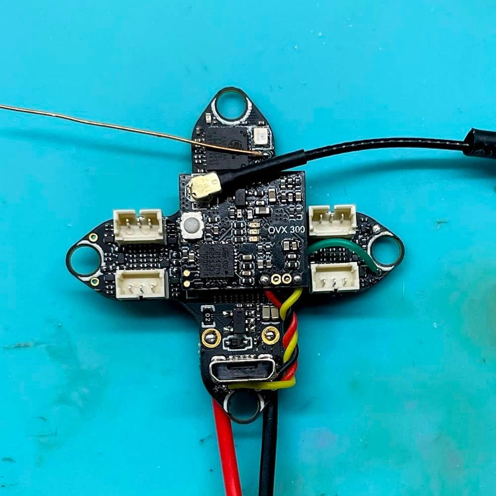
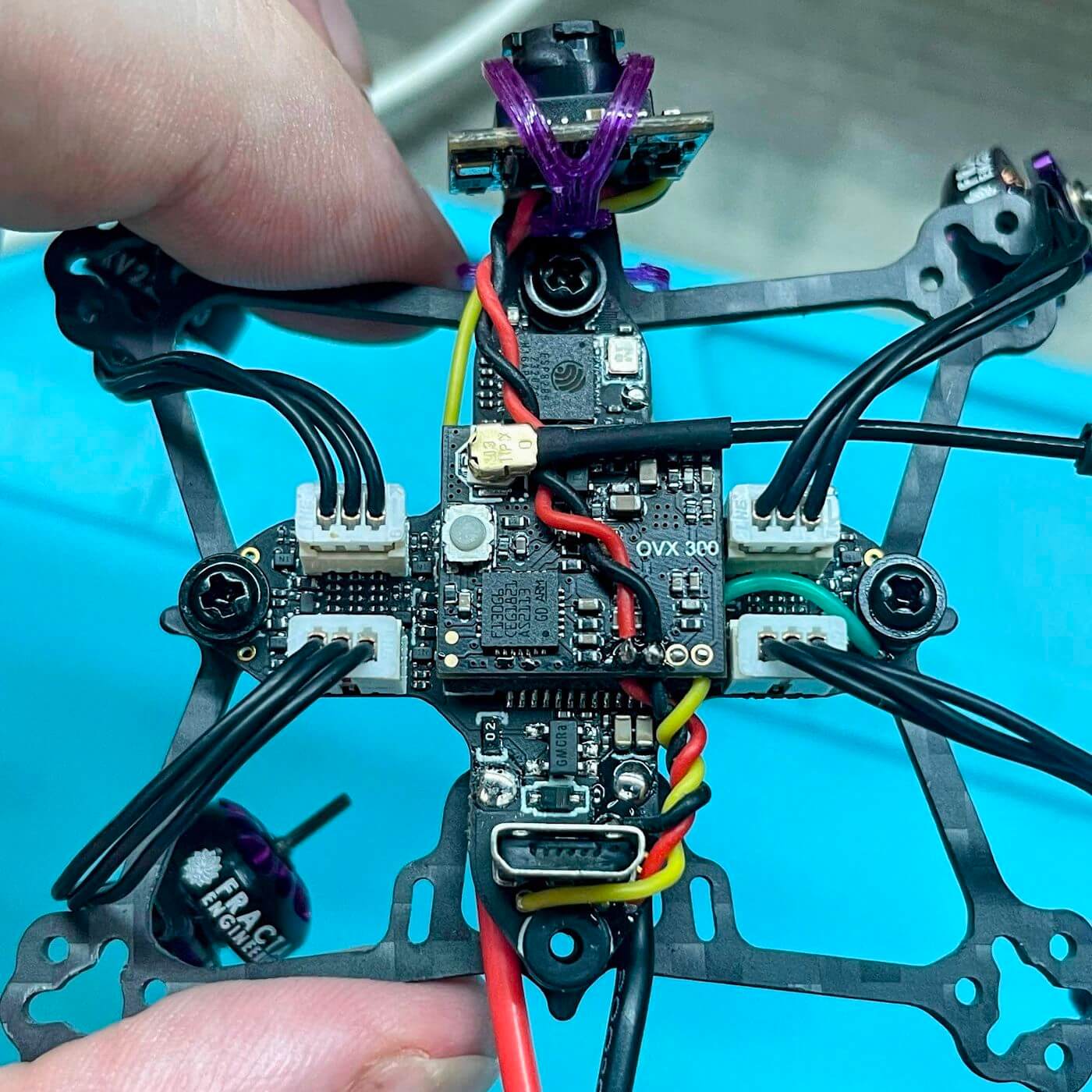
HM CrossF4 + OVX300
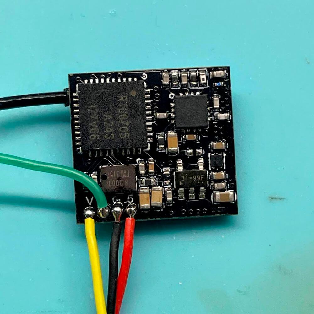
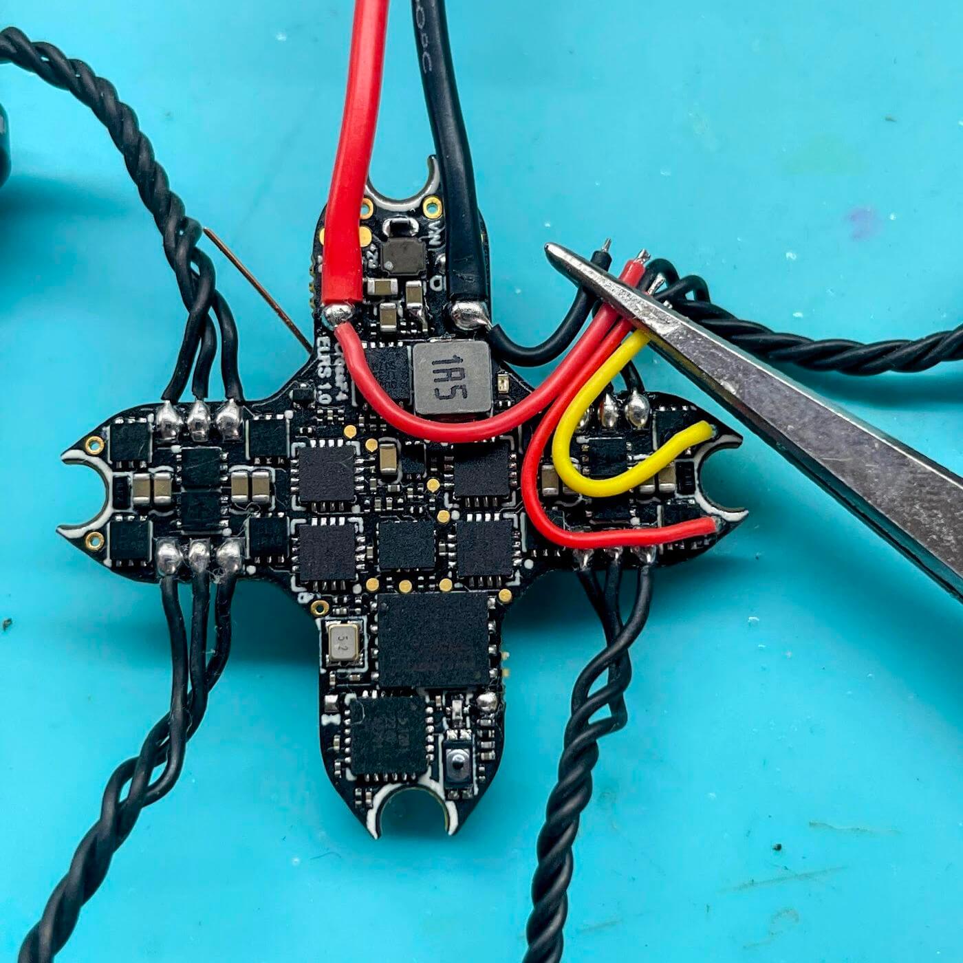
Solder the AIO pigtail flush on the bottom.
Solder the VTX wires on the bottom.
Stick the VTX on the AIO with VHB (trim the protruding top corners)
Wire the VTX. GND to the USB, then 5V, then video. And TX1 for SA/MSP
Assemble the FC to the bottom plate, USB facing UP
Use long M1.7x6mm screws, cut the included grommets top and/or bottom to clear the CF but fit the screw.
Or use short grommets with other grommets trimmings to shim it up and avoid contact with the CF
Install camera. You might need to replace/extend the yellow video wire by the one included with the FC to reach the VIN pad at the back (dumb I know)
Twist and solder the cam power leads to the VTX power
Twist the motor wires 4-5x and lay down along the CF braces
Digital Builds
HM Superbee + HDZero Whoop Lite
Solder the AIO pigtail through hole or flush on the top, leading straight back (cut gnd wire shorter)
Trim the motors right at the connector and solder on the FC
TEST MOTORS
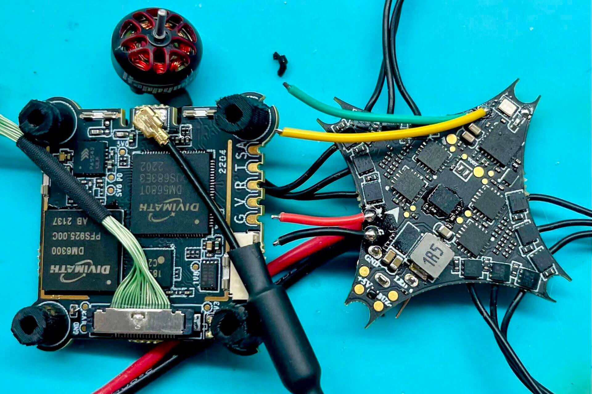
Place the VTX and FC as pictured below, with the VTX pads edge and the FC power edge facing each other
Solder on the power and uart 2 wires on the FC
Trim them about where they meet the VTX edge when placed side by side + 5mm
Install the HD grommets in the VTX with needle nose pliers (you might need to squish them a bit.)
Note they are directional; the wide slot goes on the VTX, and the flat surface facing outwards
The next step is easier if you only install the front and back ones first.
Snap on: the camera mipi (leading forward, to the left of the front grommet) and the antenna (leading backwards, to the right of the rear grommet)
Marry the FC and VTX together, and assemble the remaining 2 grommets.
Solder on the VTX wires to the FC.
Assemble the stack on the bottom plate using the M1.7x10mm screws, FC on top, USB facing UP.
HM CrossF4 + HDZero Whoop Lite
- Prepare the board by trimming off the rings around the fixation holes, about where the white silk screen ends. File down the sharp edge to tidy it up.
- Snip off the USB ground pins next to the battery pads; I recommend smoothing it up by refreshing the cut with a little solder dome to avoid cut and wear on the pigtail
- Solder the AIO pigtail flush on the bottom, leading straight back.
- Solder on the vtx power leads to the same joints
– I recommend using a NC tweezer to hold the pigtail in place - Trim off the excess motor plugs flush with the mosfets if you decide to keep them (the plugs)
- Solder on the uart 1 wires
- Trim all the vtx wires about as pictured
- Install the HD grommets in the VTX with needle nose pliers (you might need to squish them a bit.)
– I recommend starting with only the front and back one, then the sides after marriage
– Also note they are directional; the wide slot goes on the VTX, and the flat surface facing outwards - Snap on: the camera mipi (leading forward, to the left of the front grommet) and the antenna (leading backwards, to the right of the rear grommet)
- Marry the FC and VTX together, and assemble the remaining 2 grommets.
- Solder on the VTX wires to the FC.
- Assemble the stack on the bottom plate using the M1.7x10mm screws, FC on top, USB facing UP.


Mechanical assembly
Now that your electronics are all soldered up and tested and the most difficult part is behind you, let’s get it all assembled
But first a little preparation
Subcomponent preparation
Duct Separation
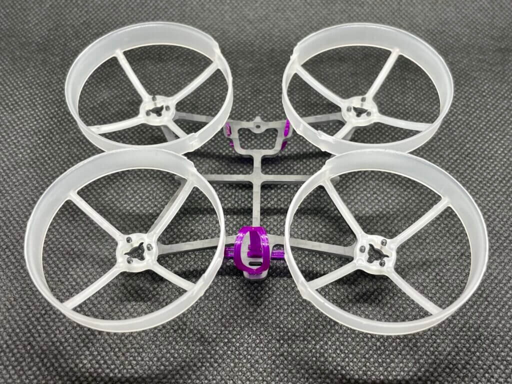
I recommend starting with marking/numbering the ducts on the untouched plastic frame so that you can install them on the bottom plate in the same arrangement.
That will ensure you keep all the smooth faces out
Once done you can start trimming the ducts off with flush cutters
Trim all the pieces connecting the ducts until you’re left with only the ducts
Final assembly
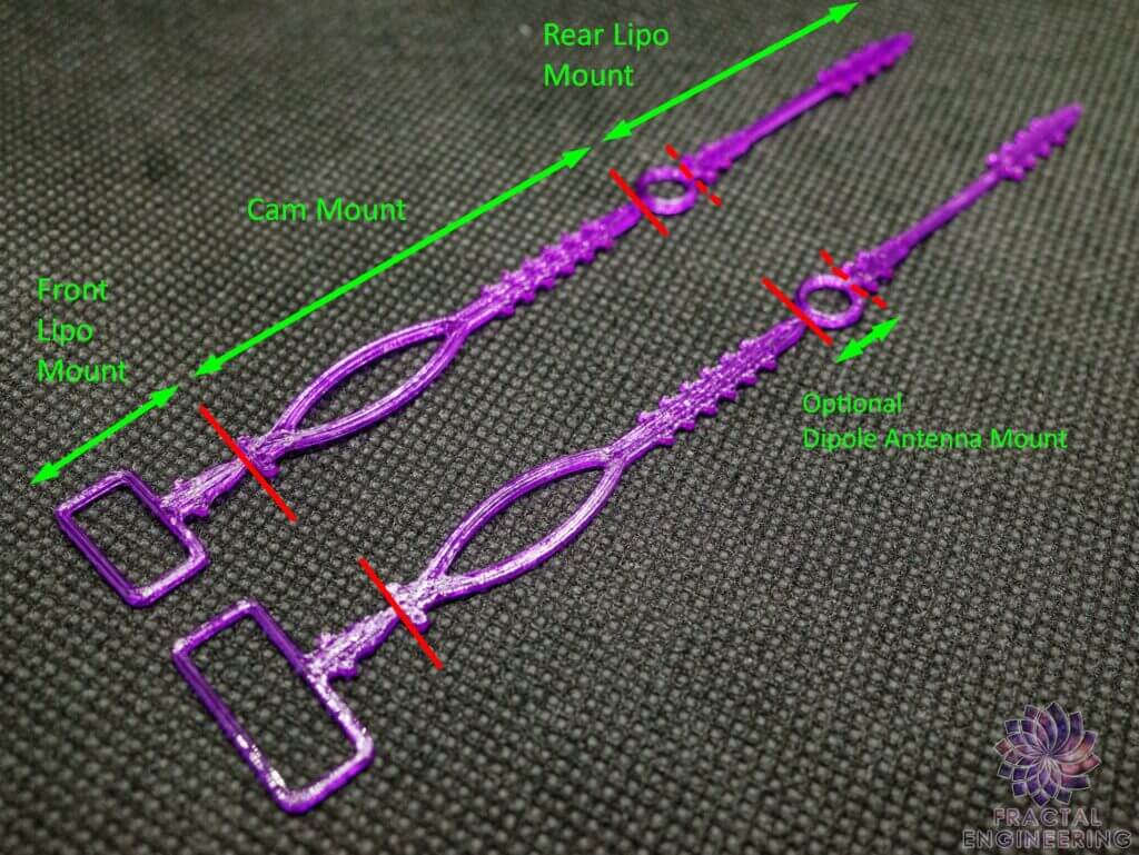
- Insert the TPU straps in their respective spots
- Screw in 1 or 2 stack screws with grommets first, then insert your FC in place (easier that way)
- Install the remaining screws with grommets to secure your FC. Make sure the screw tip stays flush with the CF and does not protrude or it will scratch your batteries.
- Attach camera (tighten the TPU strap until the camera hold firmly in place; it should hold its angle by friction alone; a little flexibility is expected)
- Twist the motors 3-4 times to neat them up so they rest on the CF brace once installed and stay out of the airflow
- Then for the motors & ducts I suggest inserting 2 motor screws through the carbon first, then while holding them in insert the duct, so you can more easily align the motor base
- Lightly tighten these 2 screws, so you can still adjust the duct to line up the hole for the 3rd screw. ALWAYS USE 3 SCREWS PER MOTOR. The motor brackets will break easily on 2 screws only.
- Repeat for all 4 motors/ducts and there you have it!
- Perform a final QC by going over all screws again, making sure the antennas are tight and secure, the TPU straps are firmly in place.
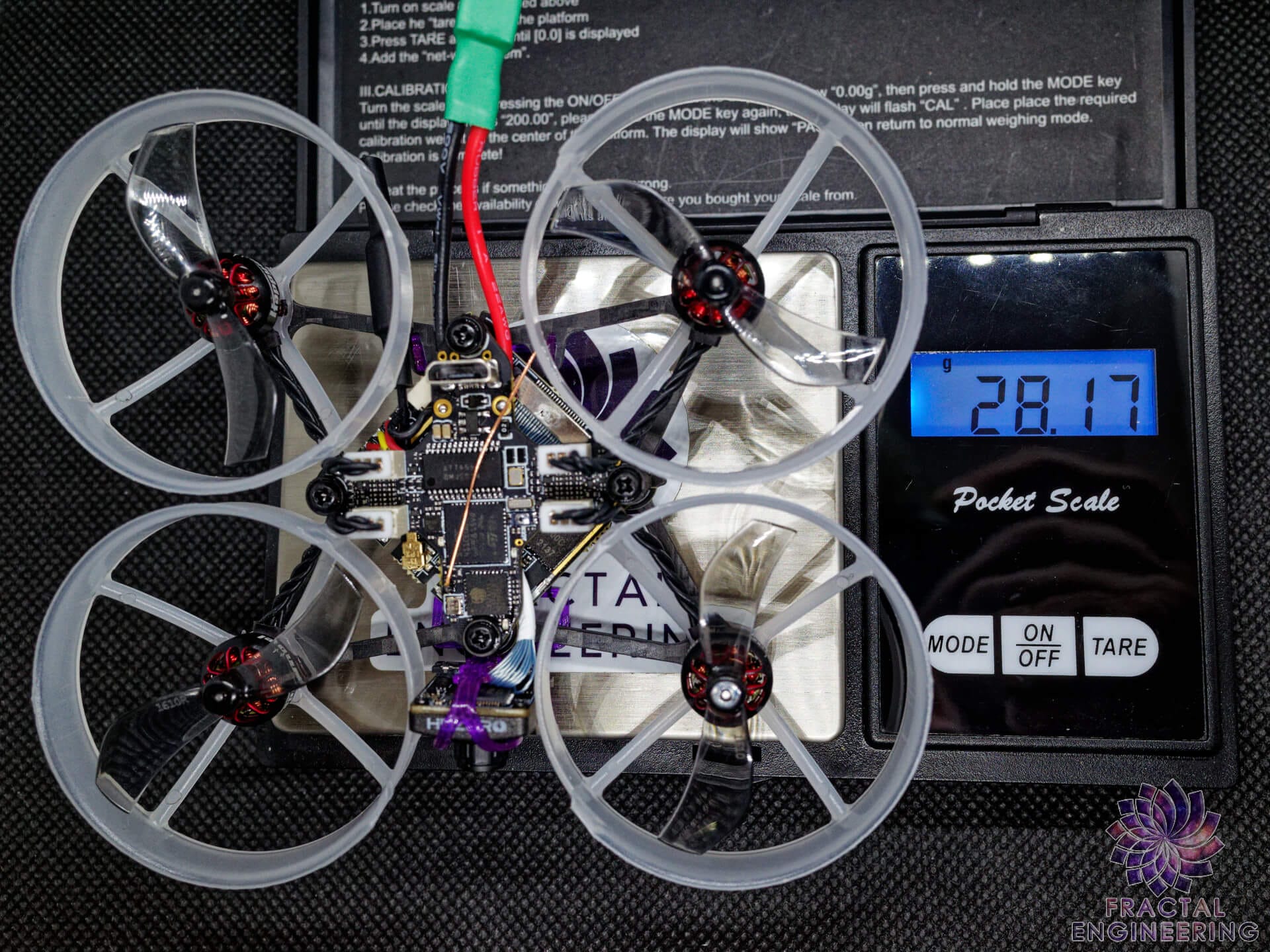
And congrats you should have a fully flyable whoop!
Now the only thing left is to program it:
Firmware installation
Finally you’ve got everything assembled and ready to go!
But there’s one last step we need to complete before you go ham to make sure all the firmware running that pup is up to date to get the most of that hardware
Core component firmware: FC and ESC
FC Firmware: Quicksilver 🥑
After flashing (more details on the Quicksilver Docs)
Optional: If you want to load a Fractal template from the template tab, skip directly to rates
1-Profile Tab
- Name quad
2-Setup Tab
- Setup serial uarts (if using external vtx must be powered on to be recognized)
- Adjust motor settings (dshot, idle, prop dir, turtle %…)
- Adjust voltage/current scale if needed
- Adjust gyro orientation
3-Motor tab
- Adjust motor mapping and orientation
4-Rates Tab
- Select a pid preset corresponding to your build
— If chosing a template start from here —
- Adjust your rates
5- Receiver Tab
- Bind your transmitter (using stick commands or bind phrase for SPI) *tip: if external RX hit 3xUP to save bind and lock protocol
- Check Channel mapping with the mixer sliders
- Setup your aux channel (2 position only) *tip: leave prearm ON unless putting it on a switch
6- OSD Tab
- Give your quad a cute name
Adjust your OSD elements
Any issues or questions? Join the Quicksilver Discord and ask there! Always happy to help
FC Firmware: Betaflight 🐝
I’ve stopped maintaining BF tunes since 4.3 in favor of the much superior flying Quicksilver firmware above that I recommend anyone to try out, with my 2-click templates.
But if you’d like to use Betaflight I’ve heard good things about the Kaack template there.
ESC Firmware: Bluejay 🐦
Go to ESC Configurator on Google Chrome (not Brave)
Plug in your FC by USB, select port and connect
Read settings
From there you may:
- Flash All to upgrade or change the PWM frequency; unless otherwise stated, latest version is typically best (true as of today with 0.21). 48kHz generally works best.
- Increase starting power and protection – I suggest 1040/1148 for O-H-5 and 1200/1256 for anything with higher than 30 deadtime
- Increase beacon and beeper strength – I like 200 on most builds, just don’t stay on it too long
- Lower beacon delay – I like 2mins for whoops so it starts beeping quicker after an eventual rxloss
Accessory firmware: Receiver and VTX
(Serial) ELRS Receiver - N/A on SPI ELRS receivers
You will find everything you need in the incredibly well-documented ELRS Wiki
Analog VTX: OpenVTX
Most OVTX come with 0.2.0 already flashed, but if you have an older vtx, be it discrete or onboard, and you want to enable MSP protocol, you may flash it here on this outstandingly simple configurator developped by our friend Hanfer of Quicksilver: OpenVTX Configurator
Digital VTX: HDZero
You will find all the latest FW releases on the official HDZero downloads page
Extras
-Link to 3D prints
-OSD logos

